V3 – CD4029 Cruise System
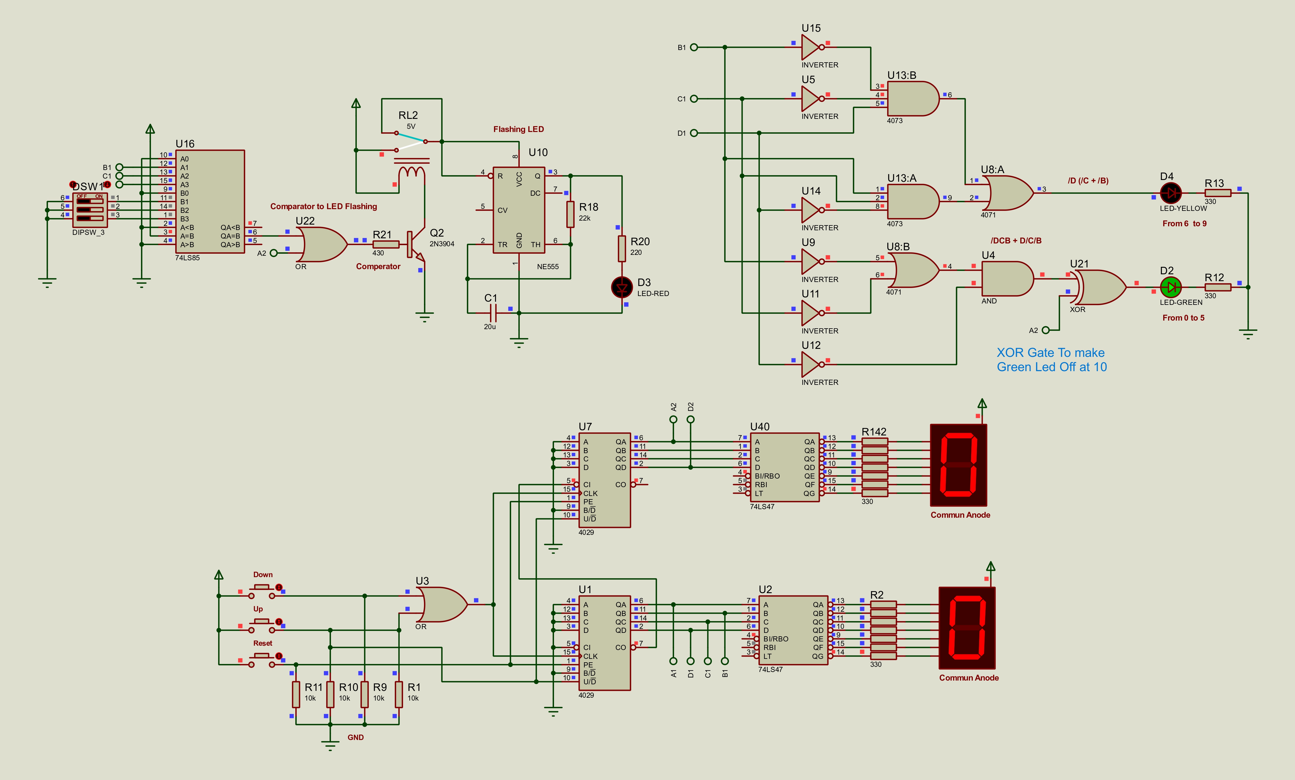
Uses CD4029 counter logic to create the cruise speed count with display decoding, comparator warning, and LED range correction.
C:\Users\henoc\OneDrive\Documents\control new\final\V3
Circuit Explanation
The CMOS CD4029 presettable up/down counter generates the speed count, decoded to the display through a 74LS47 driver. The 74LS85 comparator compares against the set speed and the NE555 flashes the red LED. Extra correction gates fix the LED range boundaries between green (0–5) and yellow (6–9).
Components Used
Schematic Preview
Proteus Project Files
V3 CD4029 Cruise System Proteus Project
V3/Project.pdsprj
Proteus simulation
Project.pdsprj
Proteus 8 Professional simulation project for V3 - CD4029 Cruise System.
Open using Proteus 8 Professional.
Circuit Schematic PDF
V3 CD4029 Cruise System Circuit Schematic
V3/Project.PDF
Circuit schematic
Project.PDF
Exported circuit schematic PDF for V3 - CD4029 Cruise System.
Truth Tables
V3 CD4029 Cruise System Truth Tables
V3/project_4029_truth_tables_updated.pdf
Truth table
project_4029_truth_tables_updated.pdf
Truth-table PDF documenting the logic used in V3 - CD4029 Cruise System.
V3 CD4029 Cruise System Truth Tables
V3/project_truth_tables.pdf
Truth table
project_truth_tables.pdf
Truth-table PDF documenting the logic used in V3 - CD4029 Cruise System.
Word Report
V3 CD4029 Cruise System Word Report
V3/project_v03_ga1_report.docx
Word report
project_v03_ga1_report.docx
Editable Word report for V3 - CD4029 Cruise System.
PDF Report
V3 CD4029 Cruise System PDF Report
V3/project_v03_ga1_report.pdf
PDF report
project_v03_ga1_report.pdf
PDF report for V3 - CD4029 Cruise System.
Limitations & special logic notes
Mixing CMOS counters with TTL drivers requires careful level handling, and invalid states above 10 still rely on manual reset in this version.