CSS370S GA1 Cruise Speed Control System
Electronic cruise speed control project library with reports, Proteus files, truth tables, circuit PDFs, schematic images, generated visualisations, and a full NotebookLM video explanation.
7
Project Versions
132
Library Files
15
Components
79
Images
Project Requirement Highlights
No Microcontroller
Pure electronic circuit solution — no MCU firmware involved.
No PLC
Industrial PLCs are excluded by the project requirements.
Green LED 0–5
Green indication for low cruise speeds from 0 to 5.
Yellow LED 6–9
Amber indication for higher speeds from 6 to 9.
Flashing Red Warning
NE555-driven flashing red LED when the set cruise speed is reached.
Maximum Speed 10
Display range tops out at 10 — simplified demonstration values.
Reset / Limit Logic
Invalid states like 11 or 99 are blocked or reset automatically.
Comparator Warning
74LS85 compares live speed with the selected set speed.
Video & NotebookLM Resources
Watch the YouTube explanation and open the NotebookLM notebook or shared artifact for this project.
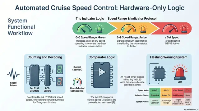
How the System Works
01
Speed Counting
Counter ICs (CD40110, 74LS192, CD4029, 74LS90) generate the simulated speed value from 0 to 10.
02
Display Decoding
Display drivers (74LS47, CD4511, 7447) decode the count onto 7-segment displays.
03
Range Indication
Combinational logic lights the green LED for 0–5 and the yellow LED for 6–9.
04
Set-Speed Comparison
The 74LS85 4-bit comparator compares the live count with the DIP-switch set speed.
05
Flashing Warning
When the set speed is reached, the NE555 astable flashes the red warning LED.
06
Reset & Limits
XOR correction and reset logic remove invalid states such as 11 or 99.
Project Versions V1 – V7
View allV1 – One Counter Cruise System
Introduces the basic one-counter cruise system concept with display, comparator, LED indication, and NE555 flashing warning.
V2 – 74LS192 Cruise System
Uses a 74LS192 up/down counter approach with display driver, comparator, green/yellow range logic, and flashing red warning.
V3 – CD4029 Cruise System
Uses CD4029 counter logic to create the cruise speed count with display decoding, comparator warning, and LED range correction.
V4 – Analog Sensor / TC7107 Cruise System
Introduces an analog sensor concept using an analog input stage and display/comparator logic for speed indication.
V5 – 74LS192 Reset Logic System
Focuses on reset and invalid-state handling using 74LS192 counters, display drivers, XOR correction, and reset logic.
V6 – CD4029 + CD4511 Cruise System
Uses CD4029 counters and CD4511 display drivers with carry/borrow logic, XOR correction, comparator warning, and reset logic.
V7 – 74LS90 Completed Cruise System with 4-bit Comparator
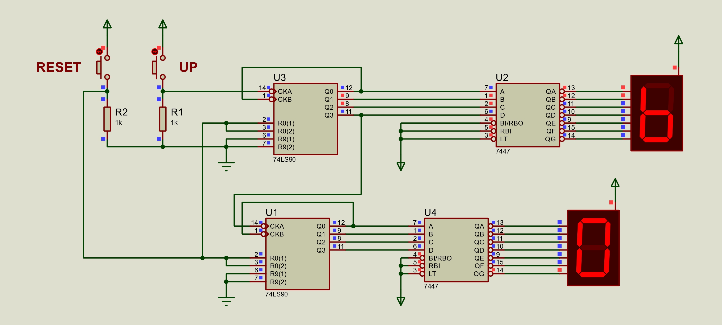
Started as a two-display 74LS90 and 7447 counter circuit and was completed with green/yellow logic, XOR/inhibit correction, 74LS85 4-bit comparator, DIP switch set-speed input, NE555 flashing red stage, and reset/limit logic.
Recent & Important Files
Full libraryCSS370S GA1 Project Template
2026_CSS370S_PROJECT GA1_TEMPLATE.docx
Root document
2026_CSS370S_PROJECT GA1_TEMPLATE.docx
Official CSS370S GA1 project report template.
Automated Hardware Speed Control Reference
Automated_Hardware_Speed_Control.pdf
Root document
Automated_Hardware_Speed_Control.pdf
Root project document included with the CSS370S GA1 project archive.
BET Project Report Guidelines
BET Project Report Guidelines.pdf
Root document
BET Project Report Guidelines.pdf
BET project report guidelines for structuring the submission.
CSS370S GA1 Project Brief 2026 Updated
CSS370S GA1 PROJECT 2026 (2) (1)updated (1).pdf
Root document
CSS370S GA1 PROJECT 2026 (2) (1)updated (1).pdf
Updated CSS370S GA1 project brief with requirements and assessment context.
NotebookLM Project Notebook
NotebookLM Project Notebook
Video Explanation
NotebookLM Project Notebook
NotebookLM notebook containing the CSS370S GA1 Cruise Speed Control project sources and AI-assisted explanations.
NotebookLM Shared Artifact
NotebookLM Shared Artifact
Video Explanation
NotebookLM Shared Artifact
Shared NotebookLM artifact generated from the cruise speed control project notebook.
YouTube Cruise Speed Control Video Explanation
YouTube Video Explanation
Video Explanation
YouTube Video Explanation
YouTube video explanation for the CSS370S GA1 Cruise Speed Control project.
V7 74LS90 Completed System Schematic
V7/7 Segment Counter_page-0001.jpg
Schematic Image
7 Segment Counter_page-0001.jpg
Exported schematic image for V7.
Generated Visualisation Preview
Gallery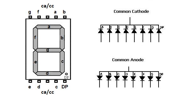
549766573 Orig
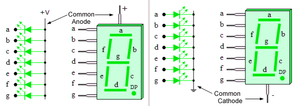
7 Segment Display Types
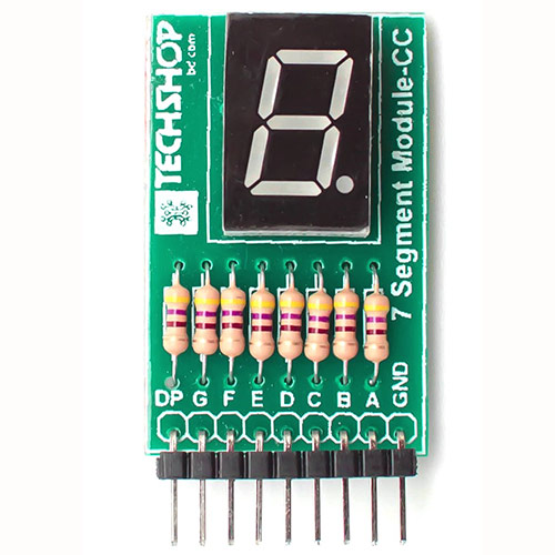
7 Segment Module CC
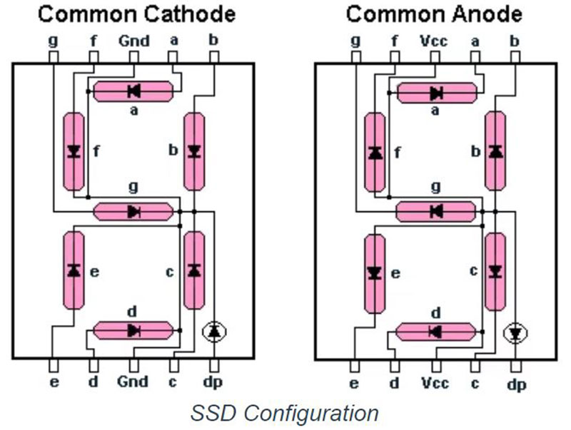
C367faff 2f5d 499b 8b49 C8aacf047184