V5 – 74LS192 Reset Logic System
Focuses on reset and invalid-state handling using 74LS192 counters, display drivers, XOR correction, and reset logic.
C:\Users\henoc\OneDrive\Documents\control new\final\V5
Circuit Explanation
Built on the 74LS192 counter chain, this version adds dedicated XOR correction gates and reset/limit logic that detects invalid states such as 11 or 99 and forces the counters back into the valid 0–10 range. Display decoding, comparator warning, and the NE555 flashing stage are retained from earlier versions.
Components Used
Schematic Preview
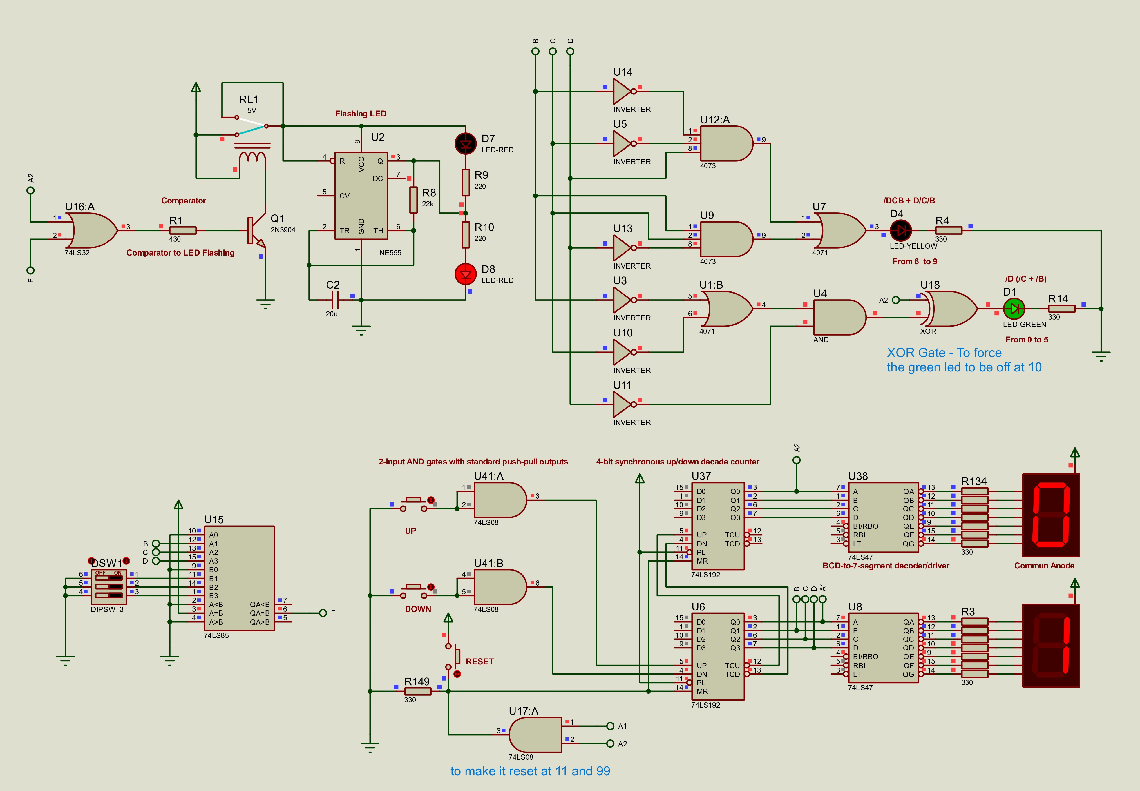
Proteus Project Files
V5 74LS192 Reset Logic System Proteus Project
V5/new1.pdsprj
Proteus simulation
new1.pdsprj
Proteus 8 Professional simulation project for V5 - 74LS192 Reset Logic System.
Open using Proteus 8 Professional.
Circuit Schematic PDF
V5 74LS192 Reset Logic System Circuit Schematic
V5/new1.PDF
Circuit schematic
new1.PDF
Exported circuit schematic PDF for V5 - 74LS192 Reset Logic System.
Truth Tables
V5 74LS192 Reset Logic System Truth Tables
V5/new1_truth_tables_updated_xor_reset.pdf
Truth table
new1_truth_tables_updated_xor_reset.pdf
Truth-table PDF documenting the logic used in V5 - 74LS192 Reset Logic System.
V5 74LS192 Reset Logic System Truth Tables
V5/new1_truth_tables.pdf
Truth table
new1_truth_tables.pdf
Truth-table PDF documenting the logic used in V5 - 74LS192 Reset Logic System.
Word Report
V5 74LS192 Reset Logic System Word Report
V5/project_v05_ga1_report.docx
Word report
project_v05_ga1_report.docx
Editable Word report for V5 - 74LS192 Reset Logic System.
PDF Report
V5 74LS192 Reset Logic System PDF Report
V5/project_v05_ga1_report.pdf
PDF report
project_v05_ga1_report.pdf
PDF report for V5 - 74LS192 Reset Logic System.
Limitations & special logic notes
Reset timing must be fast enough to make invalid states invisible on the display; the logic was further refined and combined with carry handling in V6 and V7.